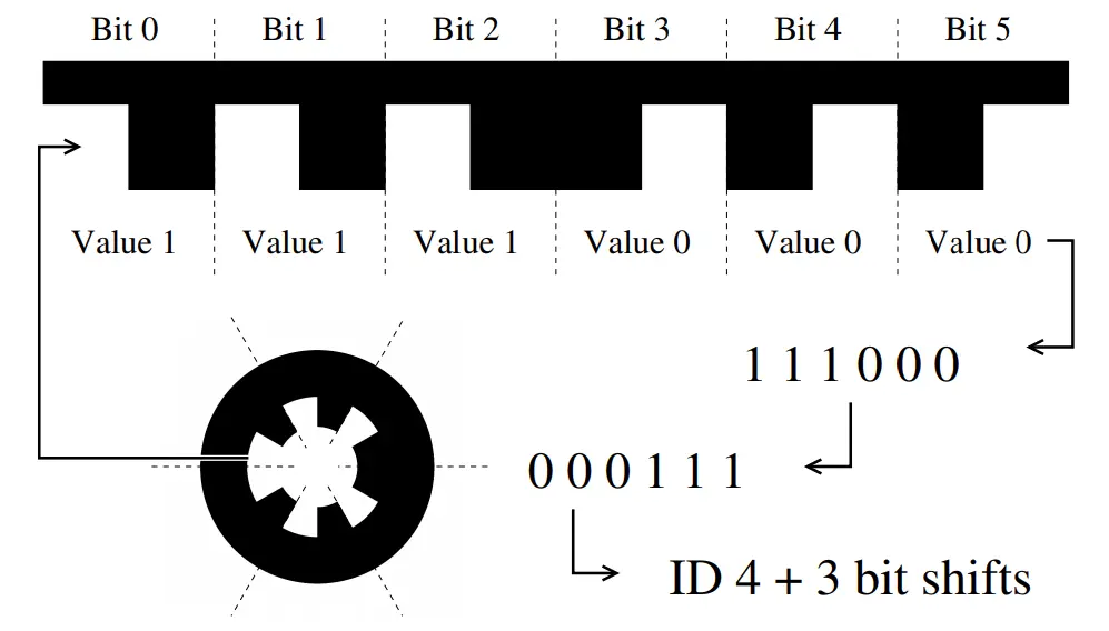
WhyCode is a circular fiducial marker system that is pretty computationally efficient. The original paper describing its structure and detection algorithm is here. Its detection algorithm works by searching images for white regions that are surrounded by black regions, flood filling them both and checking for concentricity, circularity, and region pixel size. The markers contain an ID that is explained below.
WhyCode is pretty good at detecting the position of a given marker, as long as you know the number of ID bits and the diameter of the marker before detection. However it is not very good at detecting the orientation. It is inherently difficult to determine the orientation of a planar marker in space, especially since we only have finite pixel resolution in physical cameras. WhyCode is no exception to this. When a WhyCode marker is detected, the algorithm determines the semi-axes of the outer black ellipse. (It is circular, but it is almost always seen as an ellipse because it is usually under projection - i.e. the camera usually views it from some non-zero angle.) But, the semi-axes imply 2 distinct possible orientations for the marker, and it is hard to choose between them. Each possible orientation predicts a different location for the ID sampling (shown in the yellow and green rings overlayed on the WhyCode markers above). The correct orientation is the one that is better centered on the marker.
In the original code, it seems that the “first” one is chosen - and this is the first one that is calculated as the result of some matrix operations, without regard to anything else. This makes the orientation unreliable and causes a lot of problems in any transformations that depends on the orientation. A subsequent version of the code uses variations in the arclength of each tooth. It provides somewhat better results, but is still not super reliable. My “ellipse sampling” branch of the code (shown in the top right image) uses the predictions not only of the ID sampling ring, but also the tooth edge locations, to determine which solution is more centered on the marker. It uses extra sampling lines that run from the predicted center of the marker radially outward, and attempt to center themselves on the white-to-black transitions of the teeth. This clarifies which solution is better centered. In the end, all of these methods will eventually fail as the marker becomes more and more normal to the camera, because the predictions for both orientations will be less and less distinguishable. However, there is notable improvement here.
Planar Regression
My “multi” branch of the code takes a different tactic entirely. When 3 or more markers are detected simultaneously, the detector determines the plane that connects them using the positions of the markers. It ignores the orientations of each individual marker, and assigns an orientation to the marker “bundle” under the assumption that all of the markers are coplanar.
Results
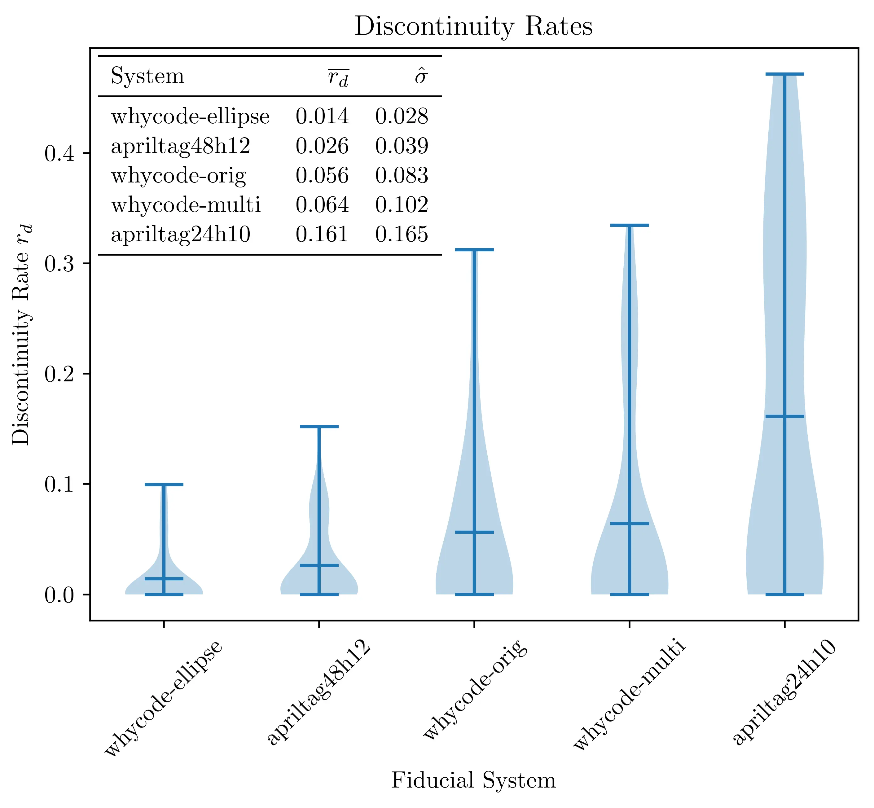
The performance of the arclength method, ellipse sampling method and multi method are shown below, where each system is tested on the same input videos as test cases. The “discontinuity rate” for each system is the amount of times that the orientation jumps between solutions, and it is best if this is low. The ellipse sampling method minimizes this with statistical significance, while the multi method shows a slight, but statistically insignificant decrease in performance from the original method. The April Tag systems shown here will be explained in another post.